For each state, I create several variants — among other things, to accommodate different hardware to attach it to clothing. You can also use the graphics files and script (download below) to generate your own models to fit whatever hardware you prefer to use. Here’s where to get the hardware:
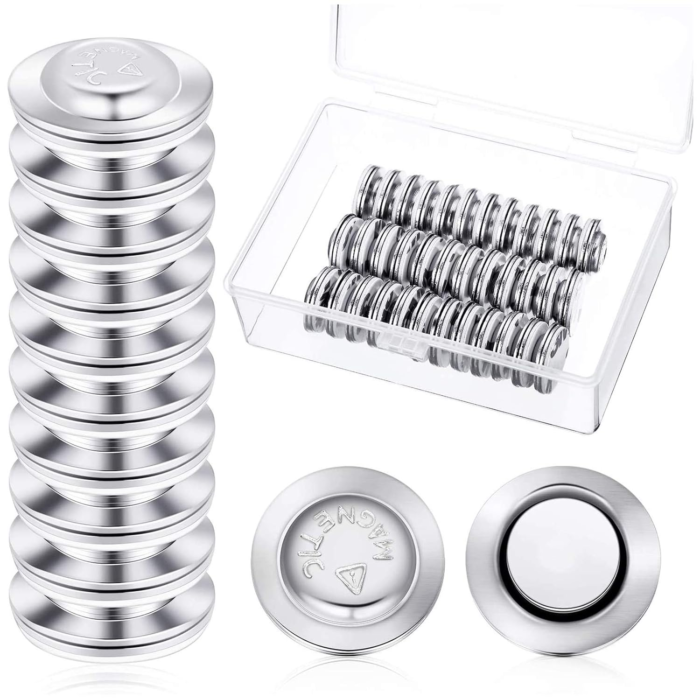
I prefer not to do business with Amazon, but these magnets are plenty strong, and cost under $.30 each, while every non-Amazon alternative seems to cost much more. They contain nickel (which some people are allergic to). Here are some alternatives at Walmart. Suggestions of other options welcome!
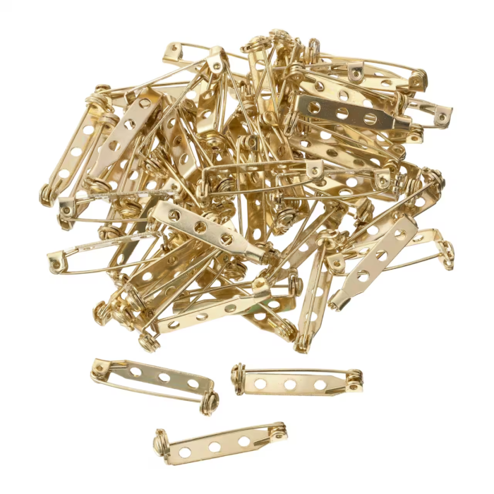
The Bead Landing brand of jewelry findings seem to all be nickel free. To attach pinbacks to badges, I suggest Aleene’s Jewelry & Metal Glue from Michaels.
To print the files
There are six 3MF files for each badge design. Three of these, with “topo” in the name, are designed for situations where color change within a layer is no big deal — such as if you’re using the Snapmaker U1 printer, which has a separate nozzle for each color. The other three, with “stack” in the name, are designed for single-color printers and multi-color machines with a single nozzle, where changing colors necessitates purging the nozzle and maybe a manual change of filament reel. These versions are designed to minimize the number of color changes by doing each layer in a single color.
I recommend 0.12mm layer thickness for these models unless otherwise indicated.

You could also print in a single color and paint after you print.
I generally try to limit each design to four colors. At least one, “LA”, uses five. When I print that, I delete the red eyes in the slicer, leaving a hole which I fill in with red glitter-glue in post-production. Or, if you’re using the “stack” files, the only limit to number of colors is your patience for changing reels.
In the comments beside each state’s ZIP file, I’ve noted the filaments I used for my sample print, as suggestions. If you use a different brand, you might still want to match the type of filament. Besides the surface texture difference between generic, silk, and matte PLA, generic PLA tends to be more translucent, so you might need more or thicker layers to fully hide the color beneath it. To illustrate this, I made sample chips of different thicknesses of white PLA layered over black. The chips labeled “s” are regular Snapmaker PLA, while “m” is Polychroma Matte, and there’s a pair with 0.08mm layer height, and one with 0.12mm.
If your print settings are appropriate to your filament, you should not need supports. The longest bridge is 17.4mm, over the hole for a round magnet. I have had no trouble printing these without support.
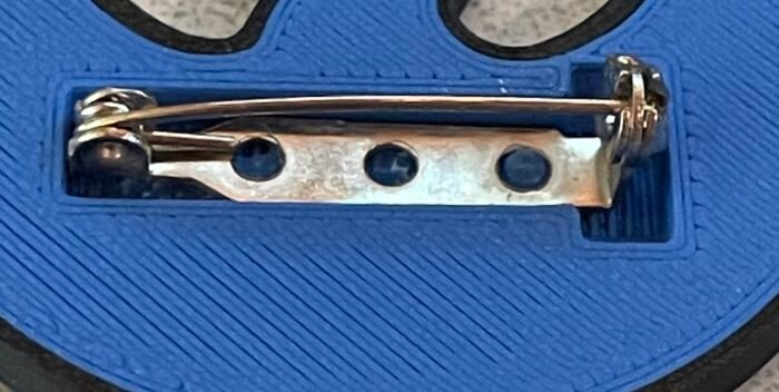
The “pin-back” models have a T-shaped hole. The intention is to put the hinge end of the finding at the base of the T, allowing space for the latch at the other end to work. You could also glue a pin to the flat-back model, but this way reduces the gap between the back of the pin and whatever you pin it to.
Files for downloading
IA, NJ, WA (American Goldfinch)
For Washington state, Iowa and New Jersey. The American Goldfinch has subspecies Eastern Goldfinch (on the east coast) or Willow Goldfinch (on the west coast), which look alike enough that they don’t need separate graphics.
Snapmaker SnapSpeed Black, Polychroma Matte Cotton White, MatterHacker Yellow and Orange. This design uses thin overlays to combine these colors to produce gray and gold in addition to those listed.
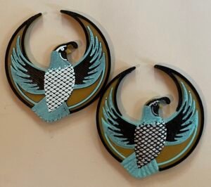
KS, NE, MT, ND, OR, WY (Western Meadowlark)
For Kansas, Montana, Nebraska, North Dakota, Oregon, and Wyoming.
Snapmaker SnapSpeed Black, Polychroma Matte Cotton White, Amolen Matte Sand Beige, Bambu PLA Silk Gold. This design uses a thin layer of the light brown over black to make a fifth color just inside the black rim, that I hoped would be brown but looks more gray. We live and sometimes we learn. Instead of the “sand beige” I think next time I’d try something a bit darker and less saturated.
NY, MO (Eastern Bluebird)
For New York and Missouri, the Eastern Bluebird.
Snapmaker SnapSpeed Black, Polychroma Matte Cotton White, Polymaker Matte Sapphire, and some junky copper silk filament that doesn’t even have a brand name. This design uses a thin layer of white over black to get a light gray from the same white filament used elsewhere on the print. You can of course choose your own colors but you might want to tweak the configuration JSON file as described below, to avoid darkening the fill layer because it’s so thin.
CA (California Quail)
California’s defender of freedom is the California Quail. I didn’t have quite the right color of filament for the blue-gray plumage, so I adjusted it with a gray Sharpie. If someone finds just the right color, please let me know. (NOTE: Polymaker Starlight Twilight gives good results but you may need to use the script to tweak the output to avoid it being a thin layer on top of black, which darkens it).
Snapmaker SnapSpeed Black, Polychroma Matte Cotton White, TonerPlastics Medallion, Polyterra Matte Arctic Teal.
KY, IL, OH, VA, WV, NC, IN (Northern Cardinal)
Several states have the Northern Cardinal as their state bird.
Design credit: Casey the American with my modifications
Snapmaker SnapSpeed Red, Snapmaker SnapSpeed Black, Panchroma Marble White, orange Sharpie on beak. The underpart of the wings and the border are supposed to be dark red but I don’t have anything to hand, so I used Sharpies to correct the color of that area.
MN (Loon, 3 designs)
Polymaker Matte Sapphire PLA, Polychroma Matte Cotton White, Snapmaker Black, Snapmaker Red.
Polymaker Matte Sapphire PLA, Polychroma Matte Cotton White, Amolen Matte Ice Blue, Snapmaker Red
Think I would go darker on the blue next time. The bird is actually black, after all. This has some details which would print better with a 0.2mm nozzle (which I don’t have).
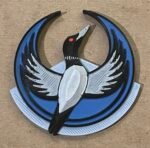
Polymaker Matte Sapphire PLA, Snapmaker White, Snapmaker Black, Snapmaker Red
LA (Brown Pelican)
Design credit: Knate with my modifications.
TonerPlastics Alligator PLA, Bambu PLA Silk Gold, Bambu Silk+ Purple, Snapmaker Black, Pop! Red Glitter Glue added post-printing.
AR, FL, MS, TN, TX (Northern Mockingbird)
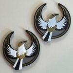
Snapmaker Black, TonerPlastics Medallion, Polychroma Matte Cotton White, 3DUniverse Silver.
NM (Roadrunner)
New Mexico’s state bird is the greater roadrunner — same fellow who gave that coyote such a hard time in the cartoons. The style is a departure from the other badges here, but seems in character for the state. The Zia sun icon, which is on the state flag, is used here with permission of the Zia Pueblo.
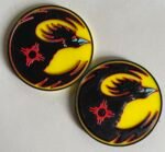
Snapmaker Black, TonerPlastics yellow, Polyterra Matte Arctic Teal, some red I forget which.
The “stack” version in this case seems to come out better in the details of face and neck feathers. If you want the “topo” version, maybe try a 0.2mm nozzle.
Using Slicer Program to Customize
These badges are generally a standard 50mm in width and 3mm thick at their thinnest point (not counting the cutout for a jewelry mount). If you need them in a different size, the easiest way is probably to resize them in your slicer software. Use the “flat back” version for this, because scaling it up in the slicer will also change the size of the hole for the magnet or whatever. Then you have to use the slicer to add whatever size holes you do need.
The same applies if you’re fine with the size, but need to use different mounting hardware than the two options I’ve allowed for.
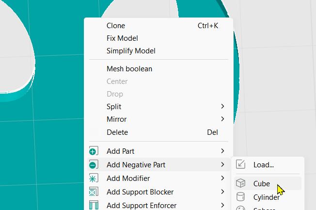
Exactly how to do this depends on your software. In OrcaSlicer, you can select an object, right-click, and use Add negative part to select from various basic shapes of hole.
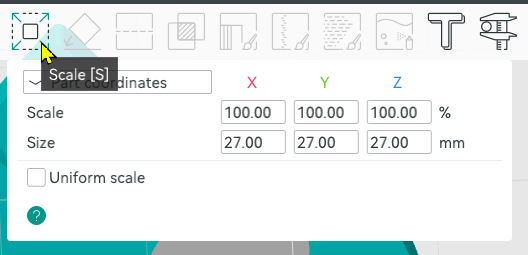
Then use the Scale function (press “S” or use the Scale icon on the toolbar). Uncheck “Uniform scale” and enter the desired dimensions.
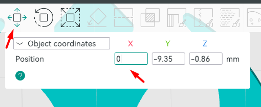
When you change the Z dimension, the hole will generally end up hovering in midair. Right-click and select Drop to place it on the print bed, where it’s needed. You can use the mouse to drag the hole to the desired position in the X and Y axes, or use the Move function (M) to position it precisely relative to the object.
To reproduce the holes my script creates:
- The hole for the round magnet is 17.4mm diameter x 1.7mm.
- The hole for the pin clasp is 27 x 6 x 2.5mm, and the bit at the end to let you work the clasp is a disk 10mm diameter, height 4mm, on its edge, just touching the bottom of the rectangular hole.
Using the Script to Modify These Designs
For more complex customizations, such as changing the topography or the order of colors in the layered designs, or making a badge from a totally new design, you can use the script I wrote to create these.
Begin by installing the latest development build of OpenSCAD, a free tool for creating 3D models by writing code. Once you have installed it, open it use menu Edit > Preferences. Go to the Features tab and make sure the features roof, lazy-union, and import-function are enabled. Also visit the Advanced tab and in the 3D Rendering section, in the Backend field, select Manifold (new/fast).
You can download the bird badge script below. The inputs to this code are an SVG file containing the image, and a control file using JSON syntax to specify what sort of topography you want or what order the colors should go in.
Unzip the above file into a folder on your PC, then to make modifications to the existing state designs shown above, unzip those files into that same directory to create subfolders named after the state abbreviations. E.g. the file bird_badge.scad goes into C:\3D\birdbadge (which I’ll call the <badge-root> folder), then the file pelican-badge.svg can be found at C:\3D\birdbadge\LA
Each SVG image file has one or more associated .json files containing the parameters that control that badge’s shapes and colors. For instance, the file that creates the Louisiana badge is at <badge-root>\LA\badge-LA.json. Here’s a partial contents of that file:
{
	"file": "LA\\pelican-badge.svg",
	"thick": 3,
	"layers": [
		{ "id": "purple", "raise": 2.88, "slope": 40 },
		{ "id": "paint", "color":"gold", "paint": true, "bg": "#606060" },
		{ "id": "eye", "color" : "red", "raise":2.88, "height": 0.54, "slope": 45 },
...
		{ "id": "rim", "color":"green", "height": 3.24, "roof": 1 },
		{ "id": "gold-bg", "color":"gold" }
	],
	"stack": "green,purple,gold,#606060,red",
	"stackbase" : 1,
	"findingLayer": "gold",
	"fill": true,
	"anchor" : "top",
	"magnetLocation": [25, 24.2],
	"pinLocation": [25, 22]
}
I’ve omitted some lines because they were repetitious.
The top-level parameters are:
- file — the path of the SVG file containing the badge image. If it’s a relative path, it’s relative to <badge-root>.
- scale — (not shown here) is a numeric scaling factor used when importing elements from the SVG. (default: 1). I’m scaling the SVG files I work on to a standard width of 50mm, but if you don’t want to bother, you can set the scaling here instead. This works in combination with the scaling setting in the OpenSCAD customizer — multiply them to get the final scale factor.
- thick — the thickness of the badge, aside from any contouring (default 3mm). This is a minimum — the script might add height to make room for the magnet or pinback hole.
- colorAlias — an array of elements of the form [ “name“:”alias“, “color”:”colorcode“ ]. This is for clarity, to create readable names to be used in place of hex codes in the rest of the file.
- layers — the object IDs and other information about the elements in the SVG file to import. In general, these should be listed in the same order they would appear in your SVG editor, front to back. This ordering lets the script know what to do when objects overlap — which one “wins”. We’ll cover the parameters for each layer below.
- stack — a comma-delimited list of the colors to use for “stack mode”, in order from bottom to top. The layer height is set in the Customizer parameters, and the bottom layer will be thicker to accommodate the finding. The bottom layer is stackbase high, and higher layers are stacklayer mm thick. If a color in the stack list is followed by “/” and a number, the layer height is multiplied by that number. E.g. “black/2.5” would result in a layer 2.5x the thickness of the default layer.
- stackbase — the thickness of the base layer if “stack mode” is active (if not specified, thick setting is used for both).
- stacklayer (not shown) — the thickness in mm of one layer in stack mode. Default 0.12mm.
- findingLayer — the color of filament that encloses the finding in contoured mode. The hole for the magnet or whatever needs to be all the same color, both for strength and so it can be printed without supports. Normally you would choose a color that already takes up most of the bottom layer. Enough of this color will be added around the finding hold to provide solid support for gluing the part in. (default = color of last layer in layers parameter)
- fill — in contour mode, if true, any remaining empty space on the back of the badge will be filled with the finding color. Use this setting in cases where the shapes might not all touch the print plate (you can hover a layer at a specified height). You can also just create this layer yourself in your SVG file and list it as the final entry in the layers parameter. (default false)
- anchor — refers to the position of the finding hole relative to the coordinates given by magnetLocation and pinLocation settings. Allowed values are “t” or “top” for top and “c” or “center” for center. (default “t”). The reason we do this if is you use the Customizer parameters in the script to scale the badge, the position of the finding hole needs to change accordingly, but its size does not. Most of these badges are “bottom-heavy” — they have a big cutout in the top half — so you want the finding as high as you can get it without overlapping this cutout. Hence, top anchoring. But center anchoring is more appropriate for other badge shapes, where the hole is maybe in or above the center.
- magnetLocation — if you select the “magnet” style in the Customizer settings, this is the position of the hole, taking into account the anchor setting above.
- pinLocation — if you select the “pin back” or “rectangle” style in the Customizer settings, this is the position of the hole, taking into account the anchor setting above.
- notes — (not shown) lets you enter a comment that’s displayed in the OpenSCAD program during customization.
The “layers” Parameter
The “layers” parameter in the JSON control file specifies the IDs of entities to be imported from the SVG file, and their colors, thicknesses, height above the printing plate, and contour in the Z axis. They should generally be arranged “front to back” as they appear in the SVG file, because this ordering will control what happens when layers overlap — the one closer to the top of this list “wins” the conflict.
Layer settings that apply to both modes
These settings matter both for “contour” and “stack” modes.
- id — the ID value of the object to import from the SVG file. IMPORTANT: SVG objects may have a “label” that differs from the ID. We need the ID value here. Look at the object properties.
- color — the color of this object. You can use any standard color name, e.g. “lightblue”, or hex color value such as “#b87333”. You can use an 8-digit color code to specify translucency. If not specified, the id value is used as the color.
- NOTE: the color is used for grouping shapes together into a single object for export. It doesn’t matter whether the color closely matches the eventual color you want to print that part in. Apart from its grouping function, it’s just used to show you the part in the OpenSCAD preview. That’s why I generally don’t use “black” as a color, but choose a dark gray instead. If the object is black in OpenSCAD, you can’t see its contours because there’s not enough contrast. But I’ll still use black filament to print it.
- paint — (default false) If true, this shape doesn’t have its own contouring, but replaces part of the surface of objects it covers. Combine with the bg parameter to know which colors are painted onto. Paint is only applied to layers below the paint layer in the layers list (even if they are the “right” color).
- bg — is applicable only for paint layers, and contains the color name or color code of the objects we want to paint. If omitted, we paint over all colors — else just where the paint layer overlaps the specified color.
When in stack mode, whether a layer is “paint” doesn’t matter to its contour, but since the bg setting modifies the shape of the layer, these settings matter in either mode.
Layer Settings for Contour Mode

When working in contour mode, we want the ability to individually control the “terrain” for each object in the layers list. In general, there are two types of layers — regular and painted layers. Painted layers take on the shape of the lower layers they get painted onto. For regular layers, we specify the shape.
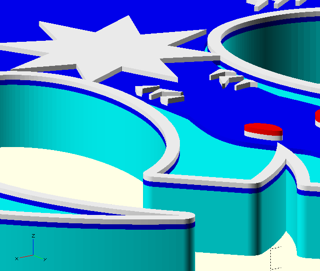
The shape of each regular layer is a variant on a “tent”. It has straight sides (whose height might be zero), below a sloping roof (the slope might be zero), with a flat top at a specified height. You can also collapse the roof down into the tent to make valleys rather than ridges, by using a negative value for roof. The above diagram shows the effects of the parameters that control this shape.
If you provide none of these parameters, listing just ID and maybe color, the result is a flat front where the colors go all the way from top to bottom. I don’t recommend this, because the resulting print will probably be weaker along the join lines between colors, so it’s more apt to break, and because even if you have a Snapmaker U1, color changes aren’t free. At a minimum, use the raise parameter to limit the number of filament changes on buried layers.
- raise — the amount the layer is lifted above the print bed. Default 0 mm.
- height — the height of the straight sides of the tent shape. Default is to stop even with the badge height established by the thick value.
- slope — the angle of rise of the tent roof. If neither roof nor slope are given, default is zero. If roof is specified and is non-zero, default is 45°.
- roof — the height of the sloped roof. If it would exceed this height, it is cut off level at that point. If the value is negative, we cut valleys into the shape to the specified maximum depth.
- method — values “s” or “straight”, or “v” or “voronoi” (default “s”). This specifies what to do on concave areas of the shape outline. Voronoi method produces curves to maintain the same slope around a point, while Straight uses flat planes, producing a wedge-shaped cutout. At the size we’re printing these, people might not notice any difference, but I think “straight” looks better for feathers, which are the most common pointy concavities in these badges. The main reason to change it is that some shapes cause an error for one method, so if that happens, try the other one.
Customizer Settings
The first value you enter into the OpenSCAD Customizer panel when you use this script, is controlfile, the filepath of the control file described in the previous section. This can be an absolute or relative filepath — relative to the location of the script file bird-badge.scad. The sample sets of Customizer parameters already populated into the script, use filepaths that assume you have installed the states into subfolders of the script folder.
The debug field lets you enable console logging of some progress/variable value messages, which is helpful to me in figuring out why things aren’t coming out as expected. It also has an option to cut the badge into a grid of cross-sectioned cubes so you can see how thick the layers of different colors are at different points (only in topo mode). This is useful when using translucency to combine colors (e.g. making gold by printing a layer of yellow over orange).
The style parameter lets you select a round hole (as for the magnets pictured above), a T-shaped pin bar hole (also see above), a flat back (i.e. no hole), or a rectangular hole.
If you select “round magnet” as the style, there’s an additional section to specify the size of that opening, with default values appropriate for the type shown above. For “pinback” or “rectangle”, there’s a set of parameters for the x, y, and z dimensions of the main rectangular opening.
In any of these cases, the plate offset setting lets you position the finding hole relative to its default position, which is specified by the control file.
The checkbox for Stack mode switches between the contoured and stack modes, the latter minimizing the number of filament changes by making each layer a single color.
Stack layer override lets you enter a different value for the expected layer height in stack mode, than whatever is specified in the control file.
The scaling setting works in either mode and lets you resize the entire model in the x&y axes (retaining the same ratio), or in the z axis (which is not locked to the same ratio as x and y). This setting will not change the size of the finding hole, but will retain its position relative to the rest of the model. The anchor setting in the control file affects this positioning.
Finally, the display setting lets you choose zero to display the whole model at once, all the colors, so that you can see how it looks all assembled. Other settings display individual color layers, though not in any particular order.
The Color change setting lets you enter a comma-delimited list of values in the form color1=color2, to override the color names used in the control file. This is most helpful when the model uses too many colors for your printer and you want to just change a color to the same as another color you’re already using. E.g. the Northern Cardinal badge uses five colors; you might enter “orange=white” here to leave the beak white, and color it in by hand after printing. Or maybe you just want to try a different color in the preview, to see how it looks.
Of course, you can also change the colors of objects in the slicer — one reason to do it here is that for the stacked mode, the number of colors also affects the height of the model, so by merging colors you can also make the print a little shorter.
Exporting your design from OpenSCAD
Once the model looks right in OpenSCAD, there are two ways to export it while retaining all the different colors as separate objects.
Export as 3MF
I generally export as a single “generic 3MF” file containing all the different colors as separate objects in one file. To do this, you’ll need a version of OpenSCAD that supports the “lazy-unions” option (and that option needs to be enabled). At the moment, that means a recent development version.
Render the model (F6 key in Windows). Then select menu File > Export > Export as 3MF. Specify the name and save the file.
This is how I produced the files in the downloads above.
Export as individual STL files
You can also export the model as a set of individual STL files, one for each color. Because we sometimes mess around with the colors so stack mode can have multiple layers in the same color, you may sometimes get more than one STL file for the same filament. Anyway, keep these files together — I suggest creating a folder. Import them into the slicer all at once, and you should be prompted with the same questions you get when importing a 3MF (Do you want to resize it to different units? No. Do you want to join them all into a single object with separate parts? Yes).
Some design considerations
Sometimes the simple “tent” shape isn’t what you want. To produce a realistically contoured 3D bird, for instance, you may want a lower “roof” on the head than on the rounded body. This is the case with the “MN” badge, if you download that as an example to pick apart. That SVG file has multiple overlapping areas that are part of the black bird shape, but different parameters to control their contours, including a higher roof for the body.
Multicolor printers typically support four colors, so I try to limit it to that when I can. An exception is the Louisiana badge, where there really had to be five, including the red eye. It’s tiny, but adds a lot to the effect. When I print it, I delete that part from the slicer and add a drop of red glitter glue there, which gives it a sparkling and determined air.
If you want to use more colors that are actually different shades of the same hue, or can be made by combination of other colors in the print, you may consider taking advantage of the translucency of the materials you’re printing in. If you do that, it may be hard to come up with a design that works for both the stack and contour modes. If using the stack mode, bear in mind all objects with the same color value are grouped into the same layer slice, but you can use the colorAlias names to define different alias names for the same color, using them to force separate layers for colors you want to lay down in differing thicknesses to cover whatever is under them to a greater or lesser extent.
For instance, say you want black, white, and a gray made by laying a thin layer of white on a black base, getting three colors from two filaments. You can define a color alias [ “name”:”shadow”, “color”:”#A0A0A0″ ] and use a stack parameter such as, “black,shadow/2,white/3” to sequence the colors in such a way that objects from layers that are specified as “shadow” colored, will result in 2 white layers covering a black layer, and layers that are specified as “white” will have a total of 5 layers of white on top of the black, which hopefully will totally hide the black in those regions.
You can also produce a stacked effect in the contoured mode by specifying the raise and height settings of individual objects to lay one over another. Or you can specify the same layer twice — once as paint and then again as an object — to get a thin coating on top of the object. For instance:
{ "id": "fill-outer", "color": "brown", "height": 0.12, "paint":"true", "bg":"black" },
{ "id": "fill-outer", "color": "black" }
This gives you a “fill-outer” shape in black, covered with a thin layer of what we are calling “brown” but we will print using a lighter-colored filament that will be darkened to brown by the black showing through.
If you do either of these things, I suggest using the opacity settings of objects in the SVG editor to approximate how the result will look when you print it. OpenSCAD preview also supports transparency, but it doesn’t work as well as one might like, so your preview may not be terribly useful in this case even if the colors in your control file include an extra two hex digits to specify transparency.