I recently bought my first multi-color 3D printer — the new Snapmaker U1. As a long-time OpenSCAD user, my first thought was to adapt some of my scripts to take advantage of this machine’s abilities.
I’m here to report on my journey, step by step. I’m hoping this will be useful to readers of different levels of experience.
My examples for this article use the Snapmaker Orca slicer program, the company’s revision of the open-source Orca system with customizations around their products. Other slicing programs also have multi-color capability, but this software seems to be the only one with support for the new U1 printer, so far.
Key takeaways
If you’re experienced with 3D printing and OpenSCAD, the following might be enough to get you rolling. If not, at least it’s a theoretical basis for the practical examples that follow.
- There doesn’t seem to be a way to transfer color information into the slicer program. Colors assigned by your script are only for previewing the object in OpenSCAD. For exporting your data, the important thing is to keep the colors separate — generate a separate object for each color. After you import into the slicer, select each object’s color and material.
- There are two ways to export your data to be imported into the slicer — as a single 3MF file, or a group of files (generally STL), one for each different color. I prefer the former because fewer files to track and fewer opportunities for error. For that, you need a version of OpenSCAD that supports the “lazy-unions” option (and that option needs to be enabled). At the moment, that means a recent development version.
- Each shape generated by a top-level script statement, is retained as a separate object. By top-level I mean the statement (a) creates a shape, (2) is not within a module, and (3) is not enclosed within another statement that modifies the shape. This affects the structure of your code. We’ll get into detail on this, but in general, it means each module must return shapes of a single color, even if conceptually you want to treat a bunch of these shapes as a single multi-colored object.
- OpenSCAD has no UI to directly display the list of objects in your generated model. If you keep the above principles in mind you can write code with reasonable assurance that you’re exporting things as separate objects. But the real acid test is importing it into the slicer.1
- Orca, and probably other slicers, have a “color painter” feature. In some cases it may be easier to ignore the coding techniques given here, let your result be a single object, then manually apply your coloring in the slicer. It’s a tradeoff given that you’ll have to repeat the painting every time you change the model, so think ahead to how much you might need to do revised versions of the code or print with different parameter values.
Note: when you right-click on an object in the Preview panel in OpenSCAD, you can view a stack trace of the code that generated that object. At first it seemed to me this should let me tell whether different shapes were being held as separate objects. Unfortunately, this doesn’t work. Sorry. The stack traces can be different but still end up with the shapes as part of the same object.
A Simple Example
Let’s go step by step through the process of creating, exporting, and slicing a simple multi-colored model of a couple of overlapping cubes. Remember, this requires the “lazy-unions” option being enabled.
The OpenSCAD Script
color("pink") cube(6);
color("yellow") translate([2,2,2]) cube(6);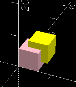
To confirm we’ve managed to generate this as two distinct objects, I rendered it (F6 key on Windows) and exported as a 3MF file (menu File > Export > Export as 3MF). I imported this 3MF file into the Orca slicer.
NOTE: as mentioned above, it’s also possible to export each color as a separate STL. However, this would require different coding. I’ll get to this.
Imported into Slicer
On import, Orca slicer showed this dialog:
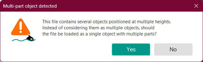
The message beginning with “This file contains several objects…” shows we were successful in creating a multi-object 3MF, and we should answer Yes, we do want a single object with multiple parts.
The lack of such a message doesn’t mean you failed. Sometimes the slicer will decide on its own to combine objects. You can confirm the object structure of your imported data by looking at the outline in the slicer.
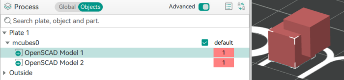
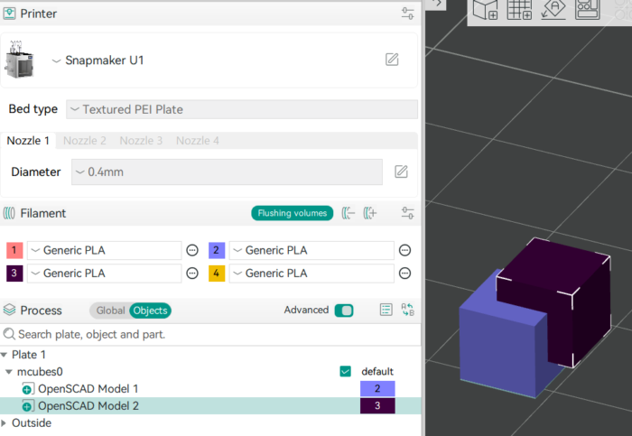
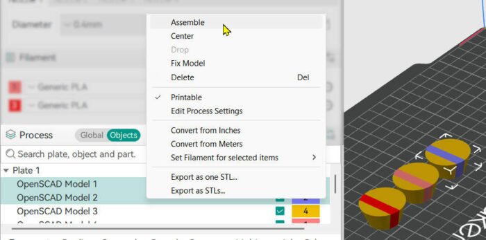
The outline shows plate 1 contains an object called mcubes0 (the name of the imported 3MF file), containing two parts, OpenSCAD Model 1 and OpenSCAD Model 2. Model 1 is selected in the screenshot, with selection handles in the preview panel showing the corresponding shape. You’ll notice the colors in the model didn’t survive the export process. That’s expected. The important thing is that the division into separate objects is retained. We’ll select their colors next.
Slicer terminology note:
- An object is a structure that’s printed as a single thing on the plate, possibly in multiple colors.
- A part is a member of an object – which might be printed in a different color from other parts of that object.
Depending how you answered the question in the above dialog (or if the slicer made that choice without asking you), you might see the different color sections of your model as independent objects instead of parts of the same object.
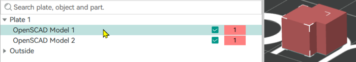
I disassembled these parts into separate objects, making the mcubes0 container go away. Two things happened. “Model 2” dropped to the print plate, because objects have to sit on the plate to be printed. And I got this warning:

To slice a model in multiple colors with overlapping (or touching) parts, the slicer needs to have them in the hierarchical object/part structure that tells it you intended for these to be in contact. I’m going to undo my change and put them back as parts of one object.
Observations:
- The parts all are imported in the same color. You must adjust their colors in the slicer software.
- Technically you’re not setting the color of an object or part, but selecting a filament for each object, out of a list based on the printer model associated with your slicer project. My U1 printer allows four filament/color selections. A project associated with a single-reel printer wouldn’t let you set different objects to different filaments because the printer isn’t capable of that.
Selecting colors for the parts of your model
I now select filaments to print this model. As it happens, I’m using different colors than the ones I encoded in OpenSCAD.
I chose filaments 2 and 3 for these two parts. These are selected from the list of four programmed filaments in the upper part of this screenshot. There are four of them because I’ve selected the U1 as my printer type, and it can hold four reels at once. I haven’t selected a specific printer, so these four colors are my expectation at the time of creating this project, which reels will be loaded when I go to print.
Previewing the Slicer Output
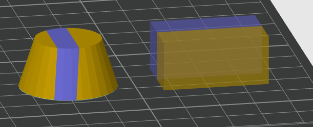
Having selected filaments, I use the Slice function (or just go to the slicer preview window – your UI may vary) to see how this will be printed. I’ve done a cross-section here (with still different colors) to show what happens when the parts overlap. The slicer didn’t complain, but just chose a filament for the overlapping volume.
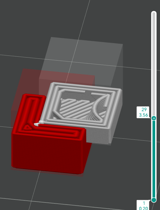
Which color takes precedence if there’s an overlap, depends on the order they’re listed in the Objects panel. In many cases, you won’t care, but if one filament is more expensive than another, or if one is translucent enough to see other colors through it, or their surfaces are flush (e.g. text that’s not raised) you have to adjust the order to control this.
If you care what color is used to print an overlapping region, change the order of the statements in your code to avoid having an overlap – then the outline order doesn’t matter. By eliminating this step in the slicer, that’s one less possible error during import and printing. More about this later.
Another thing to notice about the above screenshot: the regions printed in different colors, each have their own perimeters even where they are touching in the interior. So there’s extra material used in the bordering region between colors, compared to printing the entire object in one color. I’m not sure whether the reasons for this have more to do with the physical realities of making a successful print, or whether the slicer software is just not up to the task of doing something better where the colors touch. For the moment, just be aware of it and maybe think about writing your code to minimize the complexity of this internal border to save on material. There might be a slicer option to control this?
At this point, you should be all set to print your first multi-colored OpenSCAD project. I’m assuming you can figure out how to make the printer go, for your particular printer. In my case, the slicer retrieves information from the printer about what filaments are actually loaded, and tries to map the colors in the model with what’s currently available on the machine. If it guesses wrong, I can correct it.
Coding for STL Export
If you prefer to (or for some reason have to) export each color as a separate file, your code has to allow for displaying a single color at a time so you can export that, and manually step through each color until you’ve exported the full set. Here’s sample code to do that for the current example:
display = "*"; // [*:all, p:pink, y:yellow]
if (display=="*" || display=="p") color("pink") cube(6);
if (display=="*" || display=="y") color("yellow") translate([2,2,2]) cube(6);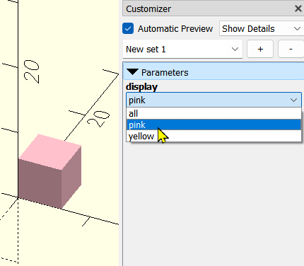
Use the “all” view to see how it looks put together, then select “pink”, press F6 to render, export that, select “yellow”, and so on.
Though I am currently always using the 3MF import for multicolor projects, I usually add this capability to my code anyway because it’s a good way to check all the parts are correct before doing the full export. And because I generally publish my code, and it might be used by someone who prefers the STL option.
How to make things go wrong
This is the troubleshooting section for your code. Let’s look at some examples of ways to structure your code that do, and do not, work to get you separate objects for your different colors.
Sub-statements
This code sample is similar to the first – I just scaled the result:
scale(1.2) {
   color("pink") cube(6);
   color("yellow") translate([2,2,2]) cube(6);
}
Unfortunately, this doesn’t give two separate objects. The rule is, each statement at the “top level” of your code that creates a shape, makes a separate object. This code contains just one top-level statement – a call to the scale built-in operation. That statement contains other statements, but they are not top-level. So you get just the one scaled object, with no division into parts.
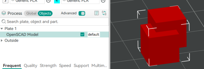
This has implications when you modularize. No longer can you write a module that returns a multi-colored object, then scale, orient, and position whatever that module returns. You have to structure your code in a way that makes it possible to return just the red part of an object (let’s say), and position it, then make another call that returns just the yellow part, and duplication that positioning so the two parts end up in their proper relative positions.
Logic statements – A-OK
Fortunately, you can use flow-of-control statements such as if and for and still have the things created within them remain independent objects. Here’s a sample:
spheres = true;
if (spheres) {
color("pink") sphere(d=6);
color("yellow") translate([2,2,2]) sphere(d=6);
} else {
color("pink") cube(6);
color("yellow") translate([2,2,2]) cube(6);
}
for (i = [0:4]) {
color([i*.25, 1, 1])
translate([-4,-4,i*3])
cylinder(3, 2, 3);
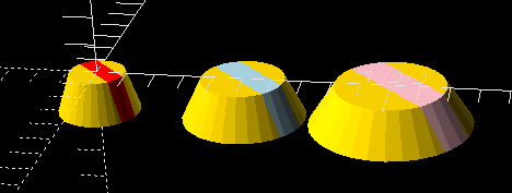
}Depending on the spheres setting in Customizer, this script either creates two spheres or two cubes, then a stack of tiny peanut-butter cup shapes. As we can see in the slicer after importing, these export as all separate objects. Yay!
We are depending on that “lazy union” option here. If that’s not enabled, some of these might well have been combined when we didn’t want them to. You can use the union statement to explicitly combine things if need be.
Multicolored Module
Here’s code that’s not going to work great with a multicolored printer.
module pbCup() {
     render(4)
     color("gold")
     difference() {
          cylinder(14, 9, 14);
          translate([1.7, 0, 0]) rotate([12,7,0]) cube([6,50,50], center=true);
     }
     render(4)
     color("red")
     intersection() {
          cylinder(14, 9, 14);
          translate([1.7, 0, 0]) rotate([12,7,0]) cube([6,50,50], center=true);
     }
}

pbCup();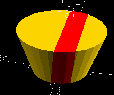
The module produces a multicolored shape like a peanut-butter cup with a pretty striped wrapper, but because there’s just one top-level statement — pbCup() — the resulting model contains just one object.
How could we code around this problem? We need two statements at the top level, one for red and one for gold. For simplicity and ease of maintenance, it would be nice to keep the code that knows how to create this delicious stripy object in a single place – one module.
So it makes sense to create one module that will return either the gold part, or the red part, depending on parameters, and call it twice.
module pbCup(color) {
     cylSize = [14, 19, 28];
     stripeWidth = 6;
     rotation = [12,7,0];
     offset = [1.7, 0, 0];
     dStripe = 3*max(cylSize);
     render(4)
     color(color)
     if (color == "gold") {
          difference() {
               cylinder(cylSize[0], d1=cylSize[1],d2=cylSize[2]);
               translate(offset) rotate(rotation) cube([stripeWidth,dStripe,dStripe], center=true);
          }
     } else {
          color(color)
          intersection() {
               cylinder(cylSize[0], d1=cylSize[1],d2=cylSize[2]);
               translate(offset) rotate(rotation) cube([stripeWidth,dStripe,dStripe], center=true);
          }
     }
}

stripe_colors = ["red", "lightblue", "pink"];
for (i = [0:len(stripe_colors)-1]) {
     offset = [i*30,0,0];
     translate(offset) pbCup("gold");
     translate(offset) pbCup(stripe_colors[i]);
}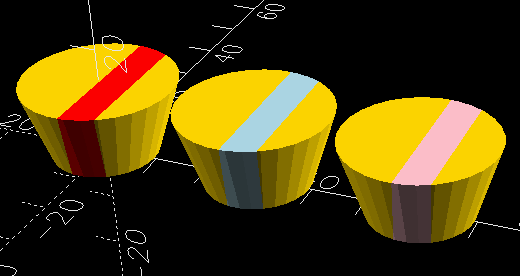
As a bonus, I made the code easier to maintain by not repeating hardcoded numbers (such as the stripe width), and I added the ability to specify the stripe color with a parameter so we could loop to make a set of differently colored objects.
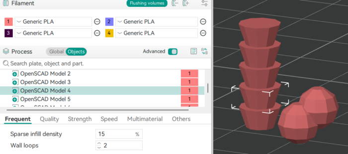
Of course, one can’t just trust that this will work – I did a test import into Orca slicer. The following screenshot shows the import after I’ve selected colors for the different parts.
So there’s good news and bad news. The good news is, these imported as separate objects, so high five (though as before, I didn’t happen to choose the same colors as the original). The bad news is, I also got this notice:

That’s because this time, when I imported, all the objects were at the same height – they all started at Z = 0. So the slicer guessed they were all separate entities, and didn’t ask me. Bad guess!
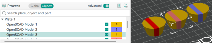
Fortunately, this isn’t hard to fix. I select the two objects that represent one pbCup, and use the Assemble function to change them into the parts of a multipart object.
I could group everything into a single object containing all six parts, but leaving them separate gives me more flexibility in arranging them for printing.
Matrix Transforms for Cleaner Code
In the previous example, we had to use separate but identical calls to translate to position the two different-colored portions of one pbCup so they ended up still in the same relative position. Notice I used the variable offset to avoid repeating the position specification. It’s always best to avoid repeating hardcoded values, so that when you have to change them, you change them in just one place in the code.
But suppose we had to do more than just translate? This is where the multmatrix function comes in handy, in combination with functions in the BOSL2 library to calculate the matrix for a given transformation, and the * operator to combine transformations into a single matrix variable. I’m going to leave the pbCup function unchanged, and just edit the code that calls it.
module pbCup(color) { ... }

include <BOSL2/std.scad>
stripe_colors = ["red", "lightblue", "pink"];
for (i = [0:len(stripe_colors)-1]) {
	mm =
		move([i*50,0,0])
		* scale([1+i/2, 1+i/2, -1])
		* rot([0,0,45]);
	multmatrix(mm) pbCup("gold");
	multmatrix(mm) pbCup(stripe_colors[i]);
}
The various functions in transforms.scad library, when called with just the positioning/rotation/move amounts, produce a matrix you can pass to the multmatrix function. The * operator performs matrix multiplication to combine those transformations. Note this multiplication is not a commutative operation — when you combine transforms through multiplication, read from right to left to find which order the operations are applied in. In this example, first they’re rotated, then scaled, then moved. If we moved the objects before scaling, the scaling would also apply to the object’s distance from the origin, so we’d get a different result.
General Considerations for Multicolor Printing
This section doesn’t have to do specifically with OpenSCAD, but has some observations from my excursion into multicolor printing in general.
Filament Waste
While it makes possible prints that you couldn’t do otherwise, multicolor printing does use more filament than the same model would when printed in a single color – in some cases, a lot more. It also takes time to change colors, which can extend the printing time considerably.
If the printer has just one hot end that’s shared by the different filaments, every time it changes color it has to purge a lot of filament from the nozzle so that the new color starts out pure.
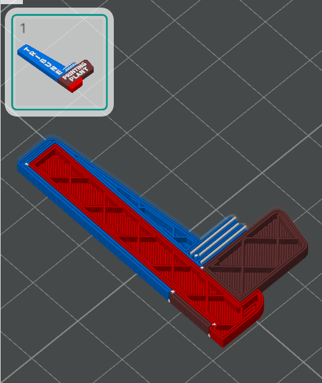
My printer, the Snapmaker U1, has four separate nozzles, so it doesn’t need to purge quite as much, but it does have to do some, because if the hot end has been sitting for a while, it might not put out an even bead when it starts up again – just like when you’re starting a print on a single-color printer and it lays down a line of on the edge of the plate to get it flowing right. But it has lay down this line at multiple heights and it can’t do it in midair, so it builds a priming tower in the corner where it can lay down a line and then move off. This tower can easily use more filament than the thing you’re printing. Here’s an illustration from the slicer of a pbCup beside the priming tower needed to print it.
To minimize waste, it makes sense to orient the model so that:
- All the color changes are in the lower layers (which limits the height of the tower),
- or so Z is the shortest dimension (same reason),
- or so the color changes are in the smallest possible number of layers (for instance the pbCup could be oriented so the stripe is exactly horizontal. It would require supports, but there would be far fewer color changes. This is especially important when using printers with one shared nozzle, since they have to purge a lot of filament for each change. Depending how you orient the pbCup, you can have two filament changes total, versus a change in each of about 100 layers (14mm / layer height).
- or print more copies of the part at once so at least they can all share the same priming tower and so, if you have just one nozzle, you do more of one color between purges.
These measures can be at odds with other considerations that might make it preferable to orient the part in a different way. The “grain” of the piece can matter when strength is needed against stresses in a particular dimension. You might be forced to print in a certain orientation so that (for instance) the part can be screwed onto a plank without the screw head possibly forcing layers apart. This could conflict with the orientation needed for economical printing.
Strength Considerations
When a model is printed all one color, subsequent layers are laid down crosswise to each other to make the part stronger. However, as shown in previous screenshot of a slicer cross-section, when parts contain color changes, each color has its own perimeter, even internally. This creates a weak point in many models – a natural “fault line” where the borders between neighboring zones align with those of layers above and below rather than crossing them, as we would normally prefer.
This problem may be worsened if the lines where the colors touch may more weakly connected than adjacent lines of the same material. That can happen because the material laid down first has more time to cool before its neighboring line is deposited, versus neighboring lines of the same color, which are typically laid down consecutively. Or, the different materials just might not stick as well to each other as they do to themselves.
Depending on the shapes involved and how likely the join is to experience stress, this might be something to think about.
If you think it might be a problem, here are some possible measures for strengthening that join:
- Change the shape of the interior wall between color regions so different colors interlock their perimeters or have fuzzy or very slanted edges, giving more crossing points between adjacent layers along the fault line.
- Restrict some color areas to the surface only, so they have stronger single-color material behind the join line.
- Print the part in an orientation that the color changes largely coincide with layer boundaries, where you were already going to have a weaker connection anyway. This may have a side benefit of speeding up printing and reducing waste due to having fewer color changes.
An example of this from my own work is this earring.
It has a stack of three thin different-colored sections, and I found it tended to break along the color boundaries. To strengthen it, I extended the bottom red part as an internal support hidden inside the other colored sections.
Slicer Bugs
I’ve noticed (and reported as a bug) that in some cases, the Orca slicer isn’t as smart as it should be about accommodating the effects of color changes. I don’t want to get into details, but this was an error in bridging the gaps in an infill when the top shell had different-colored regions. I assume other slicers might have similar problems.
I suspect there may be other issues pertaining to the interface between different colors, maybe not the same ones in all programs. Writing code that deals appropriately with multiple filaments is tricky, given worries about materials’ adhesion to other materials, the possibility that something is transparent, the fact that there’s a timing difference between different colors (so you may lay down a line that’s supposed to stick to something that’s had time to cool as opposed to a single-color model where you can quickly zigzag through a whole section of adjacent lines), the connection between a perimeter and a differently-colored infill, and other things I haven’t thought of.
For now, when working on multicolored prints, I think it’s smart to be more careful than usual about previewing the slicer output. Pay special attention to boundary regions and the edges and tops of infill.
If you do find problems, you can adjust your model or slicer parameters to compensate.
- You can manually inspect a 3MF file, which is formatted as a ZIP file containing an XML file, and check whether it lists multiple objects. But honestly, it’s easier to just import it into slicer and see what happens. ↩︎
Do you know if there is something special needed to enable multi-object export in 3mf? I am using the nightly version 2026.03.01.nightly (git b05f7f8), but my 3mf’s all combine the cubes from your example into a single object, verified by looking into the 3mf file.
I tried looking at the prefs but nothing immediately jumped at me.
Sorry. Read your description again and noticed that I’ve missed the remark about the “lazy union” thing. Works now. Thanks!
Comments are closed.