I’ve recently been improving my script to create customized 3D-printed outlet covers. I had requests that it support more types of devices and connectors, and to allow the addition of labels. I also wanted specifically for it to support the project shown here.
Using the script to produce your own designs
The wallplate program is a script written in the OpenSCAD language. I’ve written a separate page about running OpenSCAD scripts generally and printing the results, so I won’t repeat that information here.
An earlier version of this script was designed to be run online in the MakerWorld parameterized modeler, but there are just too many things one can’t do in that environment. You’ll need the standalone OpenSCAD client.
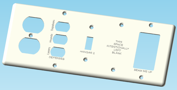
The goal of this design is to support large and/or weird wallplates that you can’t buy because they would sell too few for it to be worth anyone’s while to manufacture them — or because you’d like them in interesting colors or with custom labels.
The script supports up to five “gangs” in one long strip, with the ability to select various standard configurations of holes to accommodate whatever you have in the outlet box. Because sometimes what you need this program for is to patch over a screwup (hopefully not your own), you can enlarge the plate to cover more wall, change its depth to handle cases where the box wasn’t mounted flush with the wall, or shift the hole positions of individual “gangs” to correct for boxes that are misaligned with each other.
Next is a rundown of all the settings you use to customize this part. There are a lot of them, in part because several are repeated for each gang you could potentially add.
Overall Shape section
These settings control the shape and size of the blank plate that you’re cutting holes in for outlets and such.
Edge shape
The options here are “rounded”, “teardrop-rounded”, or “flat”.


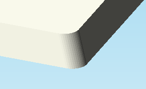
The teardrop-rounded is designed to let the plate print face-down without having a messy-looking edge. You can also print it face-up, but that requires lots of supports since the back is hollow.
Slant degrees and radius
If you choose “flat” for the edge shape, you can also set the angle the edge makes with the wall, and the curvature of the corners.
Enlarge by…
Sometimes you may need the plate to be larger than the standard minimum. These settings let you do that by separately increasing the width and height. The features are still centered on the plate.
If you need them to be off center — for instance, if you want to add a strip at the top for a bunch of text, but not expand the bottom — this is not directly supported, but you can do it by increasing the height and then setting a negative Y offset for each individual gang.
Deeper setting
We generally assume the electrical box you mount the plate on will be flush with the wall. If that’s not the case, you can use the deeper setting to adjust the depth of the edges of the plate, plus or minus.
Tolerance setting
Don’t mess with this setting unless you’re having a problem. It’s an attribute of the printer you print the part on — the minimum distance between two parts that doesn’t cause them to meld together. This is sometimes referred to as $slop elsewhere.
Labels section
Show text guides

This checkbox turns on placeholders showing where there will be label text should you choose to add some. These show placement and rotation, but are smaller than they would actually appear.
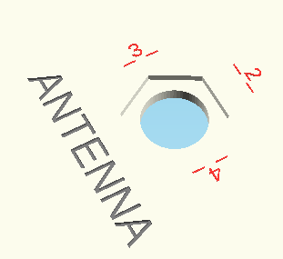
If you actually enter any label text, that will be displayed instead of the placeholders.
Label profile setting
The “profile” here refers to the height of the label text above the plate (if a positive number), or the depth of engraving (if negative).
Label font setting
If blank, “Liberation Sans” font will be used. To find a list of available fonts with styling options, use menu Help > Font list in the OpenSCAD client.
Label font size setting
This is the height of a capital letter in mm. Multiply by 4 to get the size in “points”.
Line spacing setting
The vertical space between multiple lines of text, as a ratio of font size.


All labels horizontal checkbox

If you check this box, labels which normally would appear rotated 90 degrees from the horizontal, instead are turned to upright orientation.
This setting doesn’t apply to any custom-positioned labels, which will always be in the orientation you specify.
Gang settings
There are five sections titled Gang 1 thru Gang 5. These each contain the following settings:
Gang type
high voltage

dimmer
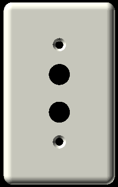
push switch
(up to 6 ports)

(up to 6 ports)

(up to 3 pairs)
(up to 3 pairs)
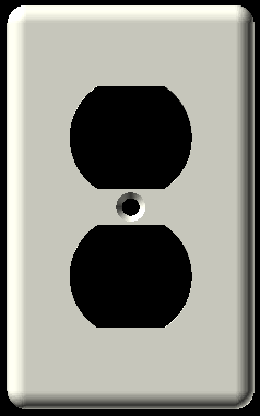
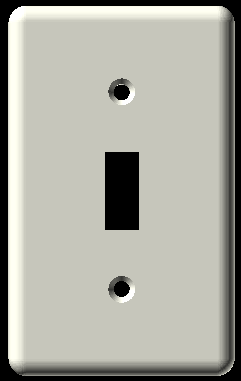
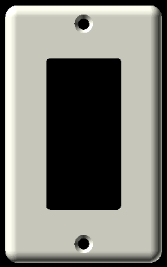
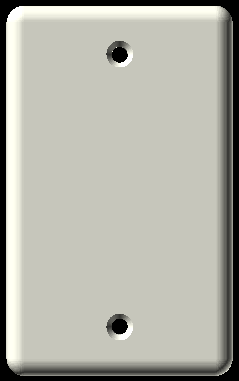
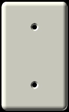
Select among US standard configurations such as “2 outlets”, “toggle”, and so on. Some notes about specific selections:
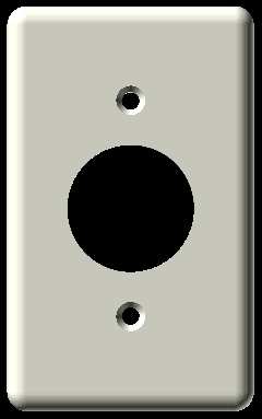
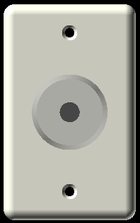
- I think the “single round high-voltage outler” style can also be used for one style of dial-shaped dimmer light switch — the kind that only turns and doesn’t push on/off. If not, please let me know.
- The “round 2-gang outlet” style, obviously, has a hole so large it requires two gang positions. You must select the “blank – yoke mount” option for the second gang.
- The “rotary dimmer” is intended for the kind of light switch that you rotate to dim and push in to turn on and off. It shows a ghost image of the knob to assist in label placement.
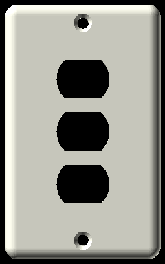
- “3 mini outlet” and “two button push switch” are less common nowadays, but I like to have old-style stuff in here so it can be used in restoration projects.
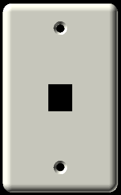
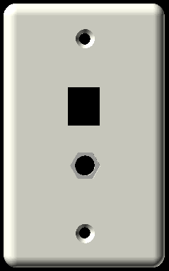
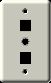
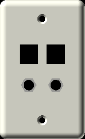
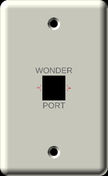
- The “keystone” style includes a clip that extends below the plate rim. This style of connector is sometimes called “Quickport.” Various types of connector ends can clip into this holder, but most commonly it’s used for a female RJ45 plug.
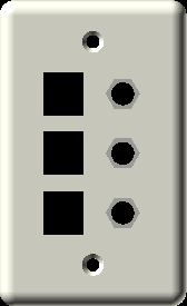
- The styles with keystone, coaxial, or both, have options to include up to 6 ports total, which is the subject of the next section.
“Multiple” setting
Gang types that include coaxial and/or keystone connectors have the option to have multiples of these, up to 6 total. The following illustrations show the layouts for Keystone + Coaxial mix:


Offset setting
In case the boxes you mean to cover with a plate are misaligned, the offset fields let you enter an X and Y displacement.
Of course it’s better to install the boxes properly so you don’t have to accommodate their wrong alignment. But sometimes it’s not up to you. Also, these settings can be helpful if you want the holes off-center on the plate — for instance, if you plan to add more text at the top than there’s room for, so you make the plate bigger, but you want all the extra height to be at the top.
Gang Labels setting
This is a complicated setting. However much text you want on the gang and however you want it placed, all that information goes into a single field, with information included to override the placement and orientation if you desire.
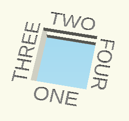
It works like this: the contents of the gang n labels field is a list delimited with semicolons. Each entry in this list is either a plain piece of text, which is placed at the next predefined text location, or, it can start with an expression of the form “{x,y,fmt}” where x and y are coordinates relative to the center of the gang, and fmt gives the vertical and horizontal alignment of the text relative to that point:
- vertical: t=top, b=bottom, _=baseline, c=center
- horizontal: l = left, r = right, c=center
- rotation: < for CCW, > for CW. There is no option to add upside down text. What sort of monster are you?
The backslash character (“\”) inserts a line break.
Examples:


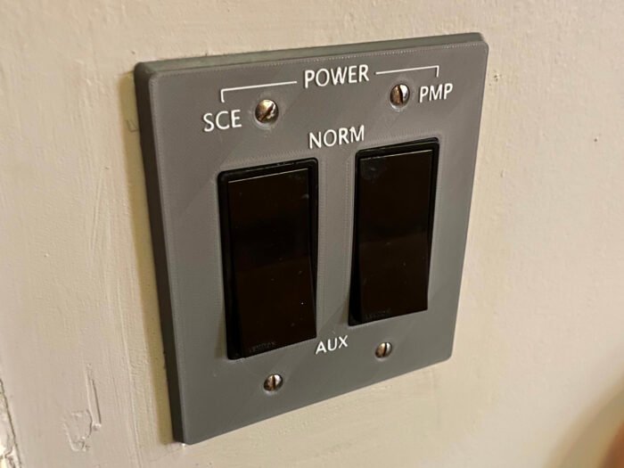
Sample project: SCE to AUX
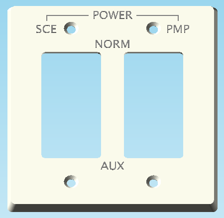
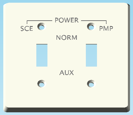
This ZIP file contains two STL files, which can be used as input to a “slicer” program to produce the switchplates shown here. The “slider” version is a little taller than standard to accommodate the text.
This is an approximate copy of a bit of a spacecraft control panel made famous when the Apollo 12 moon mission was saved from being scrubbed by the use of one of these switched. The “Signal Conditioning Equipment” (SCE) of the spacecraft was malfunctioning, and NASA engineer John Aaron suggested switching its power from NORM to AUX, which solved things and let them go to the moon.
It’s unlikely you will need to launch your house into space, but at least if you do, you now can print part of a control panel that might help.
The project download includes a JSON file with the parameters used to create these plates.
Printing Instructions
- The program will try to automatically orient the part to the best orientation for printing when you render (F6 key), based on whether you have raised text on the surface or rounded edges, both of which are better printed face up.
- They will need supports — I recommend standard grid supports. A brim is also a good idea since the downward-facing edge has very low surface area.
- The lettering is embossed — it’s the highest part of the print. The intention is that you would change filament reels at that point to print the text in a contrasting color.
- To do this, if you have a single-color printer, you must tell the slicer program to insert a pause to let you change the filament. Some slicer programs will notice this on their own and offer to insert a color change for you. Other slicer programs are unable to insert such a pause at all. Use one that does have this capability (or you could just print it single-color and carefully paint the raised lettering afterwards).
- Even if you have a multi-color printer, you might have to tell the slicer program where to change colors, since STL files don’t contain color information.