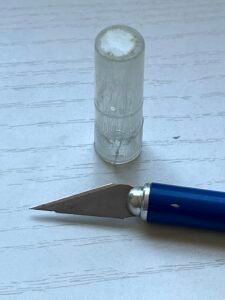
Maybe it’s a mistake to buy cheapo X-ACTO brand knives like the “Gripster”. Not only are they thinner than they might be, but the plastic parts are fragile. The cover splinters, the shaft cracks. One ends up replacing them often, which I suppose is kind of the point.
One could just start buying better quality knives, I suppose. But I’ve already got this one, and I’m not the sort of person to pass up a golden opportunity to design a part in CAD software and 3D-print the result. So I’ve replaced the broken parts of my knife with sturdy PLA plastic parts. The result is not only not-broken, but has a thicker barrel with a knurled grip, which makes it easier to handle. The cover is also designed to clip onto the other end while the blade is in use, which is great for folks like me who can set something down and not be able to find it three seconds later.
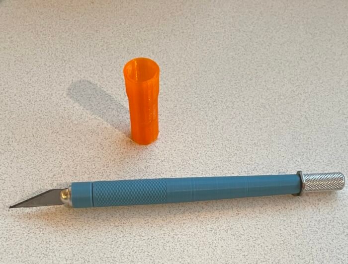
Printing this design
If you have a 3D printer, you can make this yourself. I prefer PLA, but whatever plastic you like. Resin might be more prone to crack with extended use. The STL files are attached.
I decided to design the barrel to print upright. When the barrel that comes with the knife fails, the crack always runs up the shaft, so I wanted to make the part strongest in the direction perpendicular to the greatest stress.
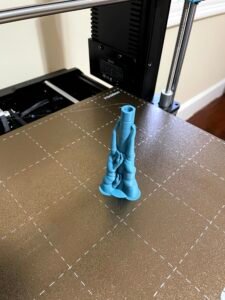
This is a little tricky to print because it’s tall and has a small contact area with the build plate. You’ll need a support structure not because of overhangs (there are none) but to hold the barrel in place as you add layers. Here’s what mine looked like on the plate:
I used PrusaSlicer software and painted on these supports — other slicer software may not have the ability to manually add supports, in which case you’re using the wrong software. You will not be able to print this file in this orientation without manually added supports. I have them touching the barrel at various points along its length.
Don’t add supports to the interior, because they may be impossible to get out. Use a surface brush rather than a sphere.
Of course, you can try printing it on its side. PLA plastic is pretty strong so you should still be okay despite the pressure applied when using the knife.
The cover is less challenging to print. It’s a bit tall also, so use a brim, but otherwise you should be okay printing it in the orientation it appears in the STL file. It shouldn’t need any supports.
Designing the new parts
I used Tinkercad for this project. This isn’t a fully capable 3D design system, but it was adequate. You can find the design there if you want to copy it and pick it apart (or customize it). Here’s the project online.
When you disassemble the knife, you’ll find the shaft doesn’t have a constant diameter. The plastic sheath that comes with the knife, on the other hand, is the same interior diameter all the way down. So much of the shaft has a gap between barrel and shaft.
This probably contributes to the tendency of the barrel to crack. It’s already made of a brittle material, and having to constantly flex as you apply pressure while cutting, can’t help.
PLA plastic is less brittle, and if the new barrel is designed to fit snugly, it need not flex. The business end will also be thicker, which makes it easier to grip and also stronger.
Here’s an exploded view of the barrel.
On the left is the complete part. I duplicated and ungrouped the entity and separated the pieces, which consist of the tip end (itself a grouped entity), the knurled grip (another group), the long tapered top (a cone), and the hole running down the shaft. The hole consists of two cylinders of different diameters, corresponding to the different parts of the metal shaft.
Tolerances
If you’re doing this sort of design, interfacing with existing parts, it really helps to have a caliper. Johnson makes a nice digital caliper that’s not too expensive.
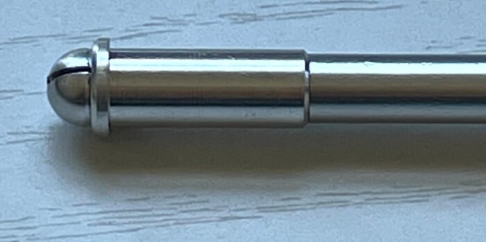
Deposition-style printers squish out a line of hot plastic, which is fairly precise but not perfect — varying somewhat depending on the exact printer, how clean the nozzle is, etc. The metal shaft of the knife (the narrower part) I measured at 6.28mm diameter. The size of the hole in the above picture is 6.60mm. The actual fit is snug. That .32mm leeway accounts for the inaccuracy of the printer — .16mm per side. This was determined through experiment and may be different for your printer, but probably not hugely different.
Of course, if you’re printing both the container and the thing contained, the inaccuracy is multiplied further. But you can generally count on it that a hole will be narrower than you specify, and a protrusion will be wider.
Groovin’ it
Now let’s explore the tip end. This is a cylinder grouped with a hole that’s shaped like a ring that’s pointy inside.
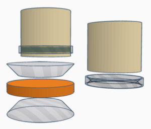
The ring is not a primitive shape. I constructed it from a short cylinder merged with two cone-shaped holes (cones in Tinkercad can be pointy or truncated). This I then turned into a hole.
For easier printing, I like to design parts so they don’t have overhangs — downward-facing horizontal bits that require a support structure, since you can’t lay down a layer in midair. That’s why I wanted a sloped edge to this groove rather than cutting out a squared-off ring shape, which would’ve been easier. Slicer programs are sensitive to even the tiniest flat undersurface.
The same pointy-ring shape is used in the cap, only as a solid rather than a hole, to fit into the hole we just cut here. Per the previous section, the ring on the cap has a slightly greater diameter than the groove on the barrel, and ditto the hole in the cap that the barrel is inserted into.
Knurled grip
The gripping surface is made rough by cutting dozens of spiral-shaped grooves into the surface. Like the groove in the previous section, I wanted the grooves to be pointy rather than square.
An alternate method of creating a knurled surface, which you can find in this video, uses a cube entity that’s been duplicated and rotated many times to make a pointy-gear shape, then stacked with a slight offset so the teeth on alternate layers line up with the gaps on the previous layer. The problem with this — from my perspective — is the resulting shape has hundreds of overhangs and the slicer software will want to generate supports for them. They don’t really need it because the unsupported span is tiny, but the slicer software isn’t smart enough yet to figure that out.

So my solution is to cut threads into the cylindrical grip section.
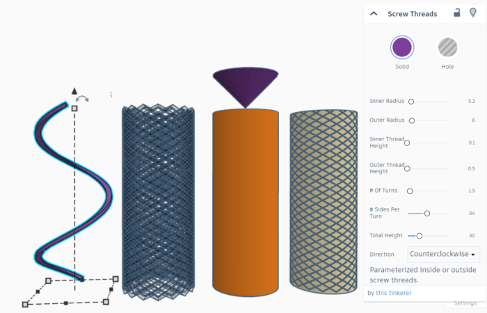
The spiral shape is actually a “screw thread” object, stretched out. I made one, then duplicated and rotated it a bunch of times to get closely-spaced spiral grooves. Then I duplicated and inverted it so the threads run in the opposite direction to make a criss-cross. Because the threads are slanty (in two ways), the overhang angle isn’t horizontal enough to prompt the slicer to add supports.
At the top, I added a cone to prevent the cylinder above the grip area from having an overhang.
